# Christmas lights hack
Table of Contents
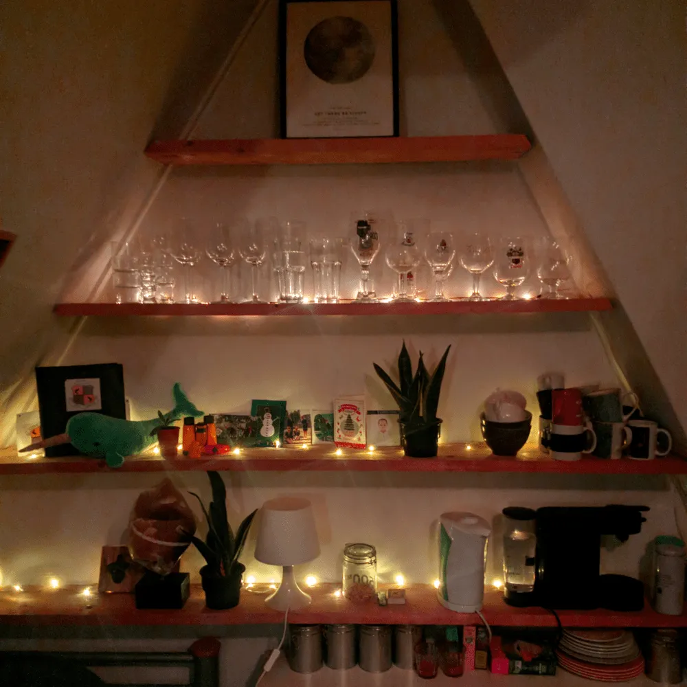
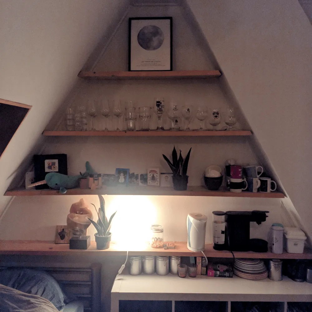
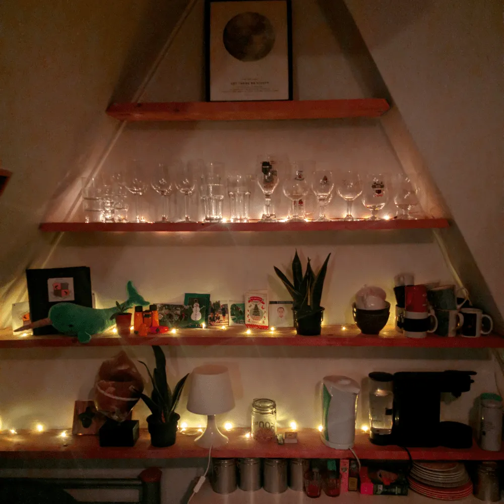
A project the bring a little more mood lighting to my room. Originally I had one Ikea light which was just a little to bright. So I decided to by cheap Christmas lights, but these required batteries and had to be switched off individually, too much effort. So I hacked them be cutting of the batteries and connecting them to an ESP controller such that I could control them via Home Assistant with just one button press.
Before and after
Shopping list
| Item | qty | price |
|---|---|---|
| Wemos D1 mini | 1 x | 1.50 € |
| 2N2222 transistor | 3 x | 0.10 € |
| 1k resistor | 3 x | 0.10 € |
| 30x15mm perfboard | 1 x | 0.20 € |
| DC-DC Buck converter | 1 x | 0.30 € |
| Wire | ||
| Christmas lights | 3 x | ~1.80 € |
Tools
- Soldering essentials
- 3D printer
Build log
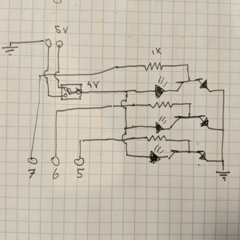
Every good project of course starts of with a good plan. For this a draw a circuit, which I then tried on a breadboard which seemed to work fine. Initially without resistors, but this caused the ESP the heat up.
The circuit design works as following. There are three LED’s placed before transistors, these transistors control the flow and allow us the digitally switch the LED’s. The transistors are connected to GPIO 5-7 with a resistor to limit the current. The LED’s are powered from a DC-DC buck convert to proved them with 4.5 volts equivalent to 3xAA. The buck converter is connected to the 5v and ground pins.
Construction
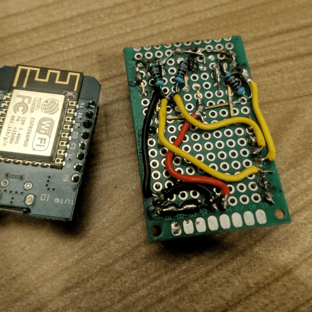
It became a bit of a mess because I mirrored the pins incorrectly at first. After that I also had the add resistors to the already finished board. But everything still fitted within the footprint and I called it good enough
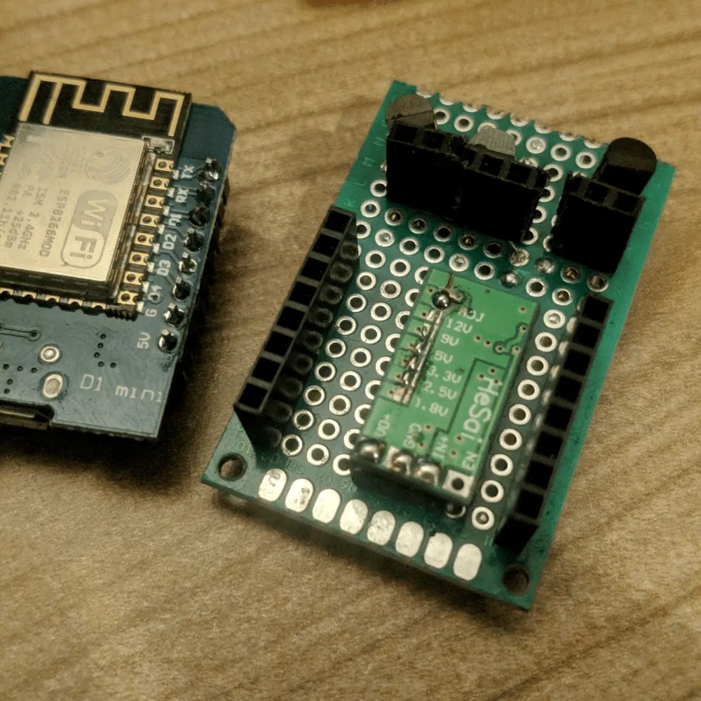
On the other side are all the headers and the buck converter. The buck converter is solder the the board the make it more low profile and fit under the ESP. In the converter the traces at adjust are connected allowing me to turn the pot meter on the other side the sed the voltage. This was set to 4.5V. The top headers allow us to plug in the Christmas light.
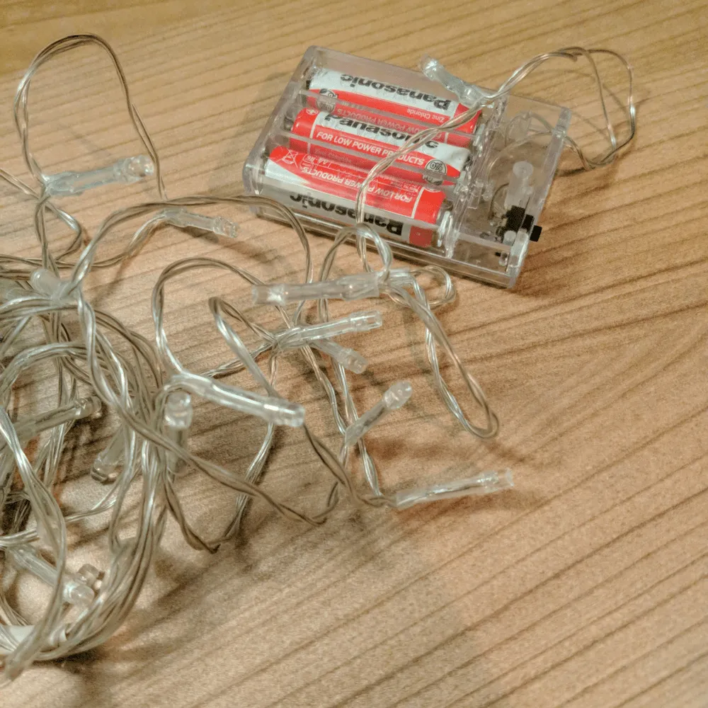
Then the lights, these are cheap store bought Christmes lights. All we have to do is cut of the battery pack and connect a male header to them. I used these connectors because these were the smallest connectors I had around. I also created some wire extensions to connect the light to the controller these are just simple wires with headers connected to them.
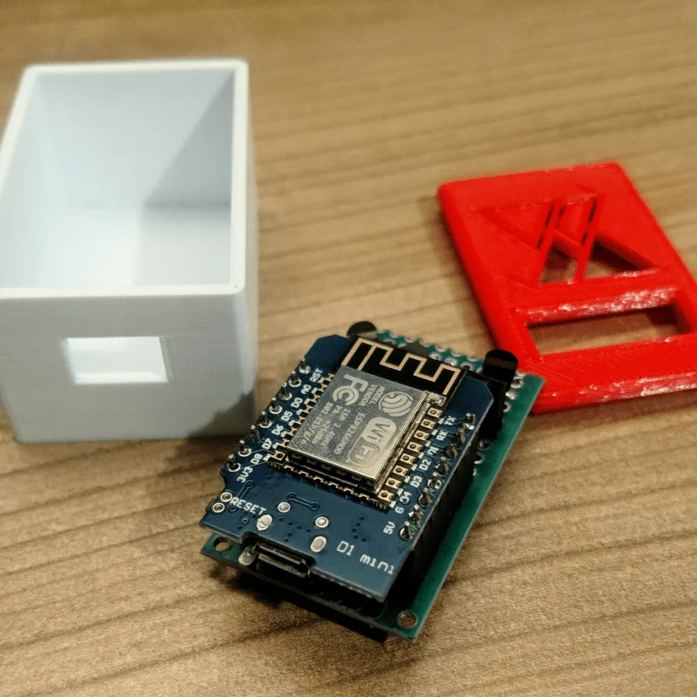
Then it becomes time to create an enclosure. The electronics are just housed in a simple box with two holes. One for the USB and the other for the light. The logo is cut out to allow more heat to escape, it looks nice as well.
Home Assistant
Now the construction is finished we can add the code. Some we will use this as in integration with home assistant we can use ESPHOME which allows use to define its functions with just one YAML config.
esphome:  name: christmas_lights  platform: ESP8266  board: d1_mini_lite
wifi:  ssid: "WIFINAME"  password: "PASSWORD"
  # Enable fallback hotspot (captive portal) in case wifi connection fails  ap:    ssid: "Christmass Ligths"    password: "FALLBACKPASSWORD"
captive_portal:
# Enable logginglogger:
# Enable Home Assistant APIapi:
ota:
output:  - platform: esp8266_pwm    pin: 12    frequency: 1000 Hz    id: pwm_output0  - platform: esp8266_pwm    pin: 14    frequency: 1000 Hz    id: pwm_output1  - platform: esp8266_pwm    pin: 13    frequency: 1000 Hz    id: pwm_output2

light:  - platform: monochromatic    output: pwm_output0    name: "shelfTop"  - platform: monochromatic    output: pwm_output1    name: "shelfMiddle"  - platform: monochromatic    output: pwm_output2    name: "shelfBottom"
With that flashed we can now use new smart lights. I use the lights with an automation which turns them on when the sun is down. But there can be many examples of interesting use cases.